Synthetic images of your inspection station, with the exact right answer for every pixel.

For vision teams and integrators who need to know where their pipeline breaks before the line shows them. Camera, lighting and part are separate, swappable models.
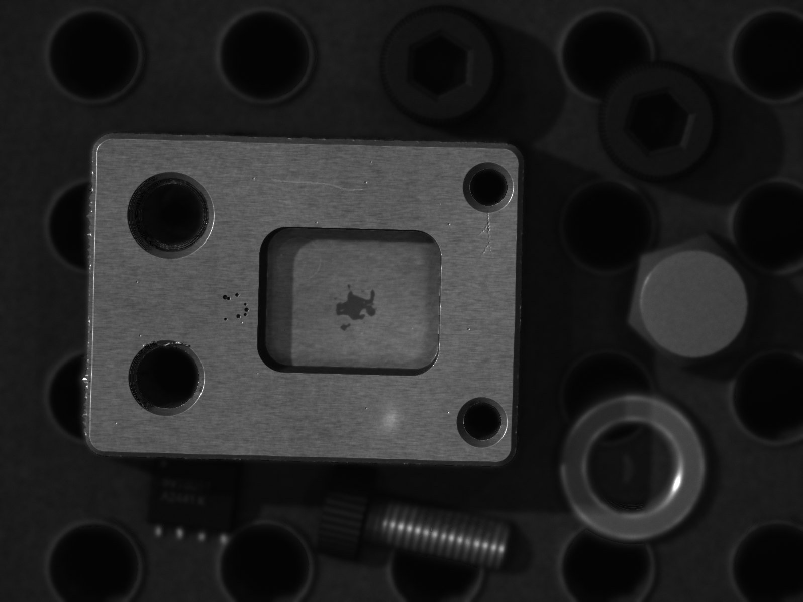
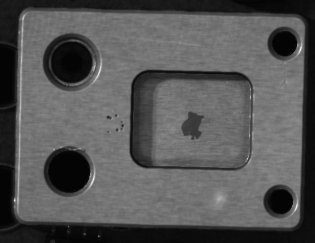
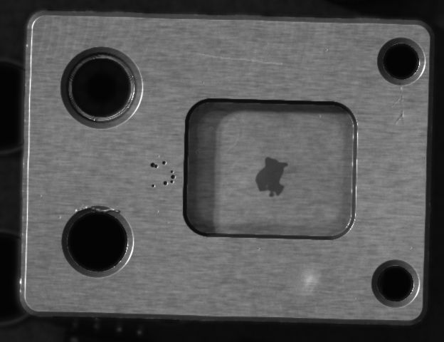
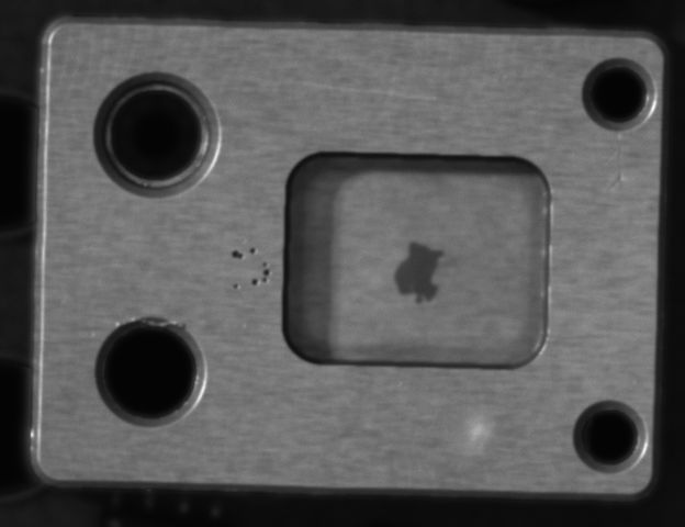
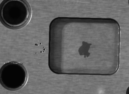
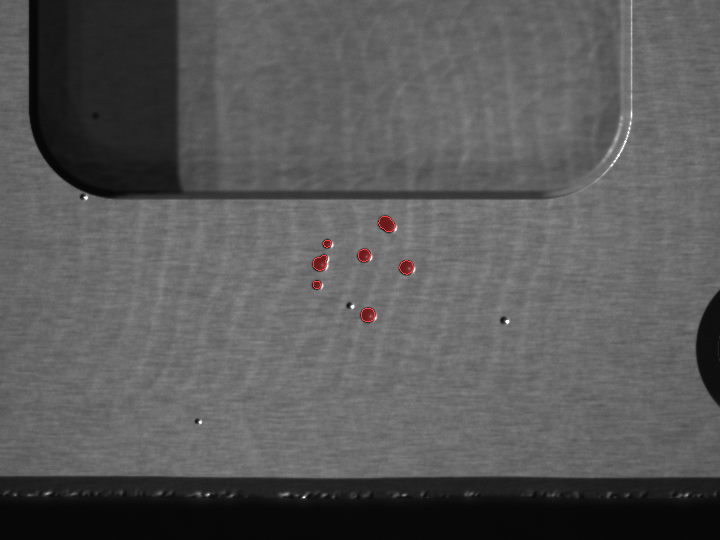
Synthetic camera image: milled aluminium part with six injected defects on a fixture plate, rendered, not photographed.

One scene, three swappable components

Every image below comes from the same model. Change the camera, the light or the part, and the image changes with it.
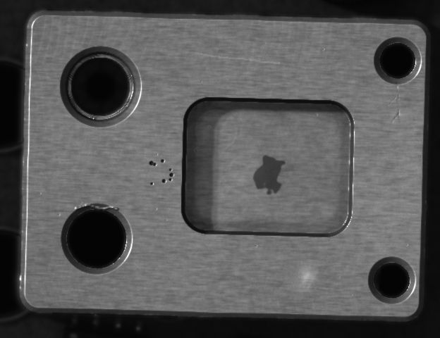
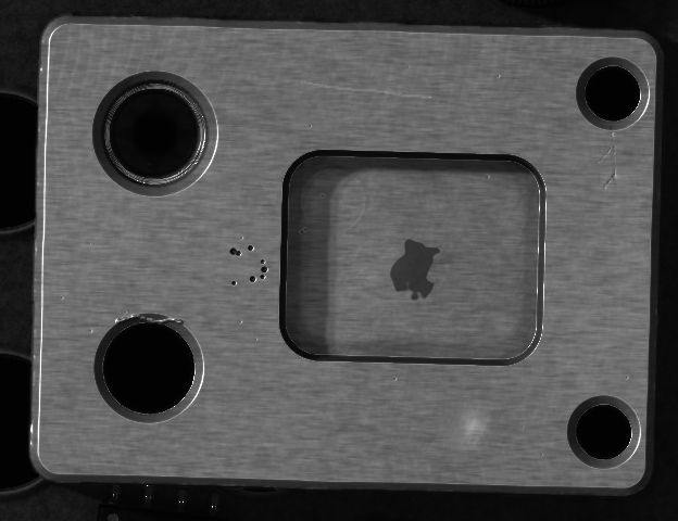
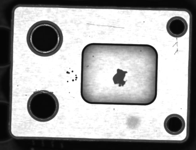
Camera: thin-lens defocus, vignetting, shot, read and dark noise, 8-bit quantisation.
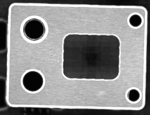
Lighting: radiance at the lens, with cast shadows, before any camera.
Part: height map in mm, from 0 to 8.2.
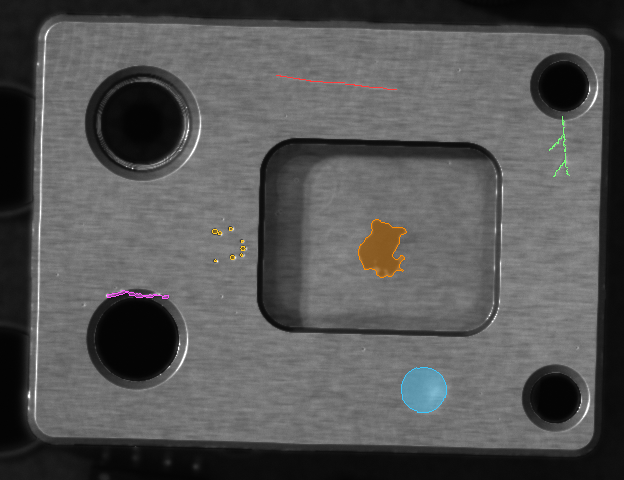
Ground truth: exact defect masks over the camera frame.
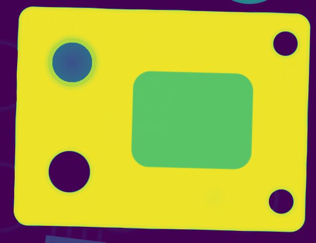
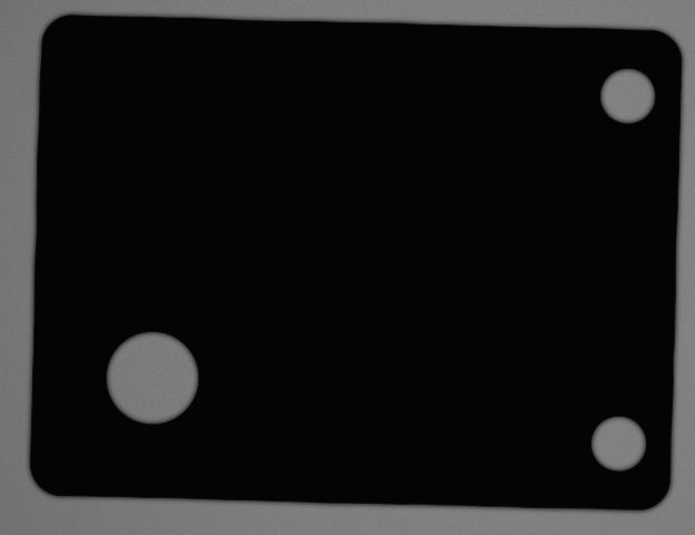
Ground truth: object class per pixel.

What only a simulation gives you

One parameter at a time, everything else fixed, and the truth known.

Focus series
Focus plane at the fixture, 6.9 px blur on the part top.
4 mm above the fixture, 3.4 px.
At the part top, 0.0 px.
12 mm, 3.3 px.
12 mm, 3.3 px.

Exposure series

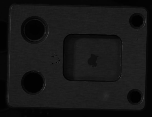
2 ms: no clipping.
2 ms: no clipping.
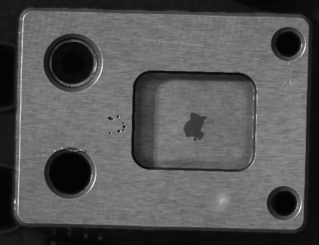
8 ms: 0.1 percent clipped.
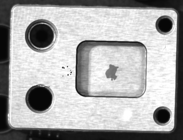
16 ms: 19.9 percent clipped.
32 ms: 82.6 percent clipped.

Light-angle sweep

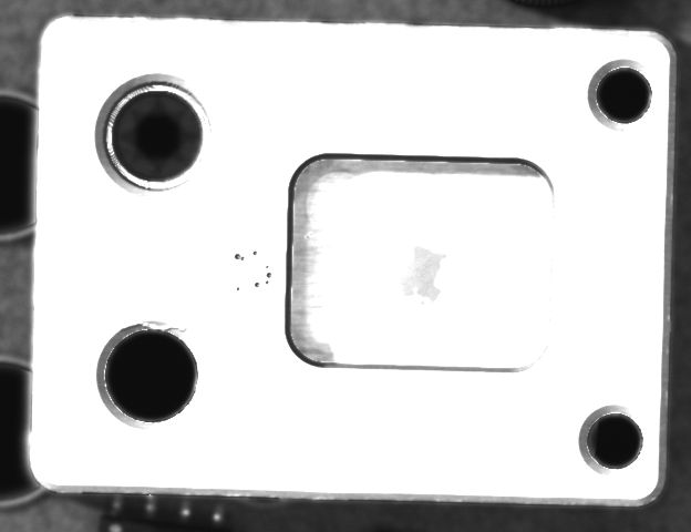
Bright-field ring, 70 deg.
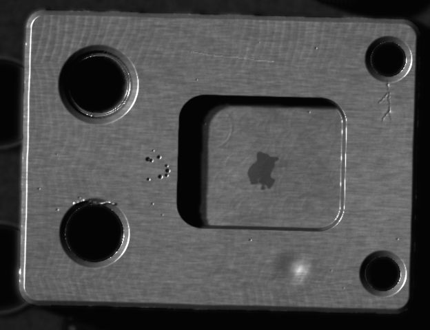
Side light, 45 deg.
Side light, 45 deg.
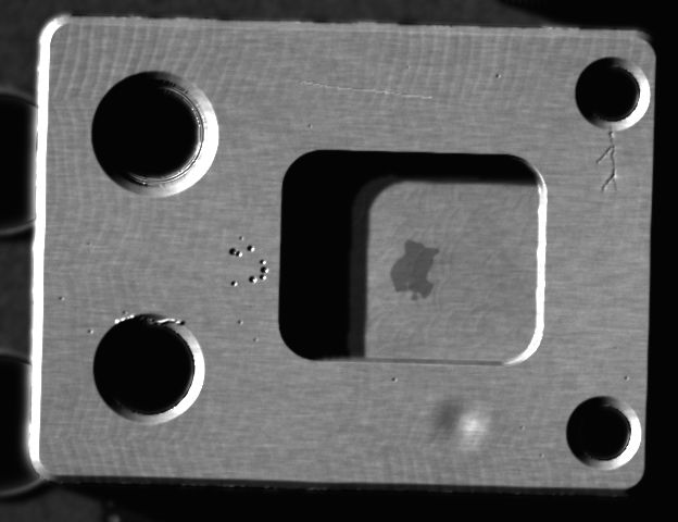
Side light, 25 deg: shadows lengthen.
Dark-field ring, 12 deg: scratches glow.
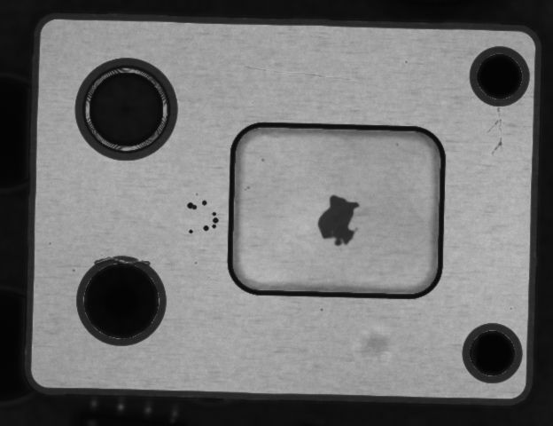
Diffuse dome: stains stand out.
Backlight: silhouette only.

Noise and gain

0 dB, 8 ms.
0 dB, 8 ms.
12 dB, 2 ms.
12 dB, 2 ms.
24 dB, 0.5 ms. Same grey level, 1:1 pixels.

Defect injection with exact masks
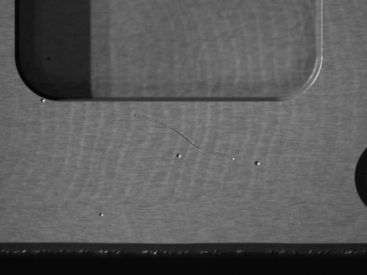
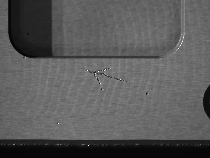
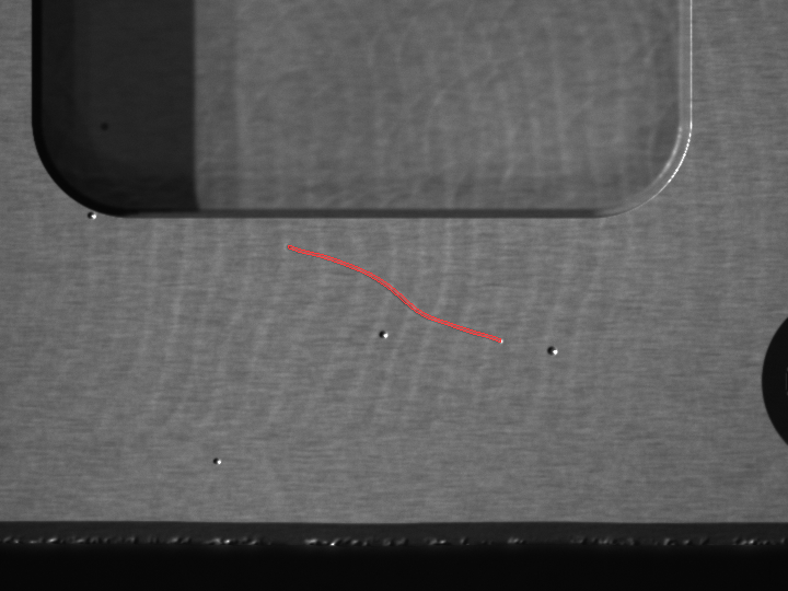
Crack, 2.4 mm.
Crack, 2.4 mm.
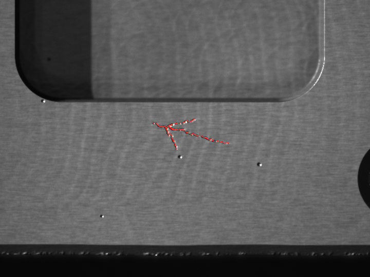
Its mask: 805 px.
Its mask: 805 px.
Scratch, 3.5 mm.
Scratch, 3.5 mm.
Its mask: 819 px.
Its mask: 819 px.
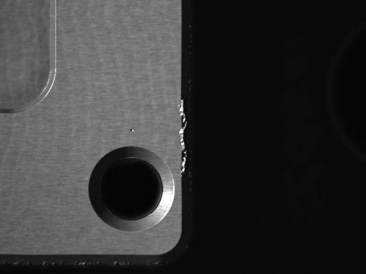
Burr, 2.4 mm.
Burr, 2.4 mm.
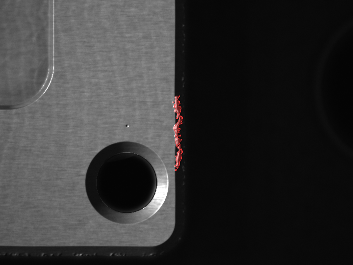
Its mask: 1344 px.
Its mask: 1344 px.
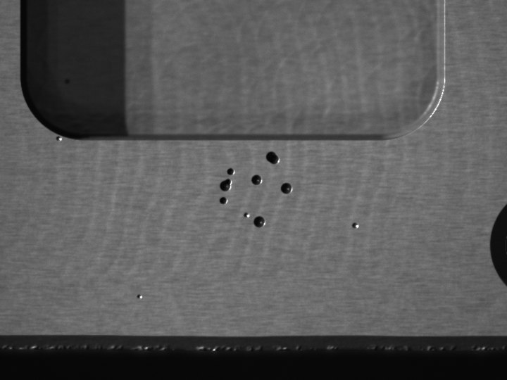
Pore cluster, 1.8 mm.
Its mask: 929 px.
Its mask: 929 px.

Pose sweep

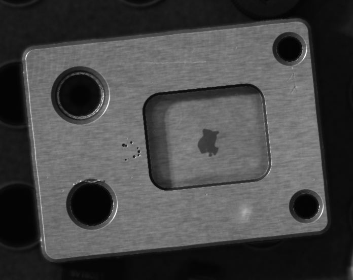
Rotated -6 deg.
Rotated -6 deg.
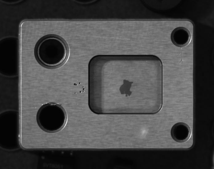
Nominal.
Nominal.
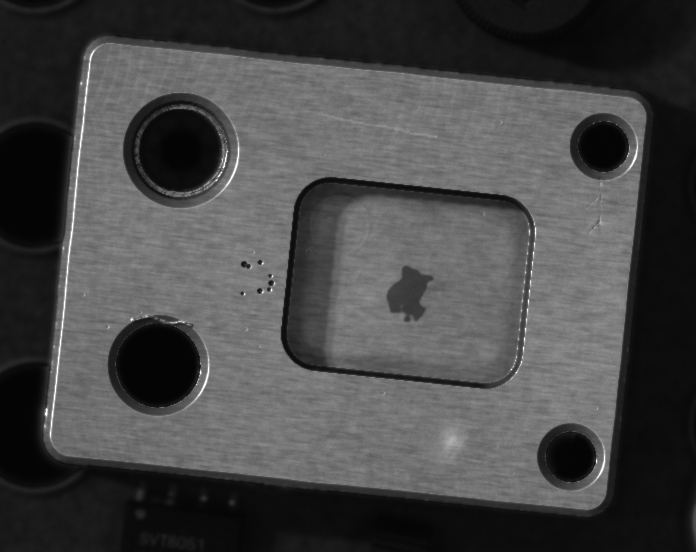
Rotated +6 deg.
Rotated +6 deg.
Shifted 1.5 mm, 1.0 mm.
Tilted 4 deg: top face leaves the focus plane.

The dashed region in the pose images is the inspection ROI of a fixed program. It does not move with the part.

Stability analysis

Your pipeline runs on image sets that I generate under varied, controlled conditions. You get a robustness report: where it holds, where it flips, and by how much.

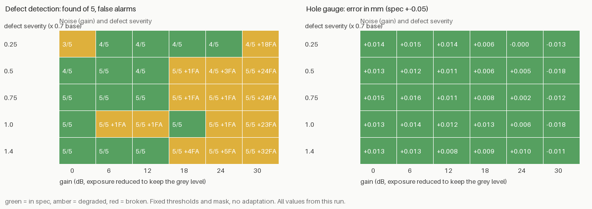
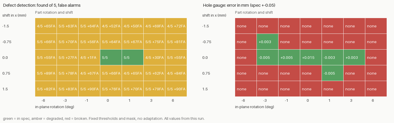
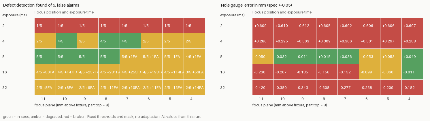
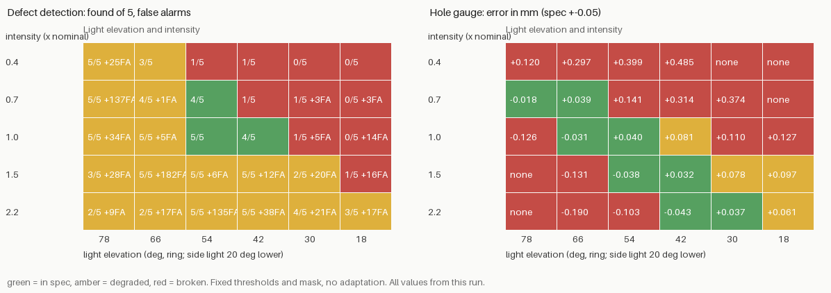
The heat maps show one fixed inspection program over four sweeps. Each cell is one condition, each colour a detection rate.
Open the stability report

Heat map: detection rate over focus position and exposure time.
Light elevation and intensity.
Gain and defect severity.
Part rotation and shift.

A worked example: does the twin match the camera?
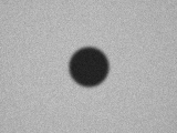
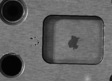
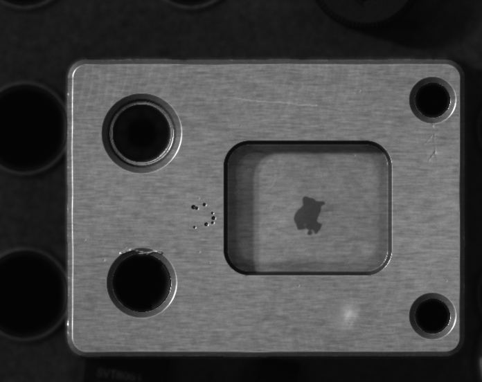
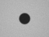
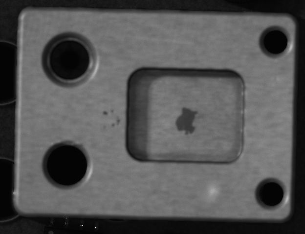
Reference image 1 of 10: a plate with a dark bore, synthetic
One of 10 reference images of a synthetic station.
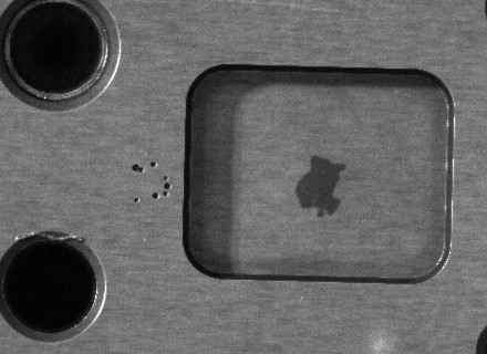
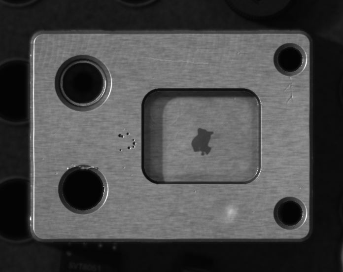
Twin render of the same plate with the true bore outline
The twin render of the same plate. True bore: 36.0 px, measured 35.86 and 35.88 px.

Services

  • Synthetic twin of your station. A model of your camera, lighting and part that renders images on demand.
  • Benchmark and regression image sets. With exact masks and measurements, for regression tests and for comparing algorithms.
  • Stability analysis. A robustness report for your pipeline.
  • 3D and OCT. Sensor-level simulation, scoped case by case.

Remote, with confidentiality agreed before any images are exchanged. Tell me your station in the form and I reply in person.

3D and OCT. There are no images of these on this page yet. Ask, and I show what exists.

About me

I am a machine-vision software developer. My work is industrial inspection, 3D vision, OCT, and high-precision and multi-sensor setups.

I build the twins in code, with an AI-assisted loop. I check every result myself and sign off what you receive.

You talk to the person who builds it.

Send an inquiry

Name your camera, optics, task and software. I reply with what is possible.

Please do not send customer images here. We agree on the exchange after a confidentiality agreement.

Questions

What if the twin does not match my real images?

The fidelity check compares noise, edge width and brightness of the twin with your real images. Where they differ, the report says so, and I say when the twin cannot be trusted for your case.

Are my images safe?

They stay confidential and are used for your job only. Confidentiality is agreed before the first exchange, and I delete them on request.

Which software works with the image sets?

Anything that reads image files. The ground truth comes as masks and a measurement table.